Resources / Automation Fundamentals

Automation Fundamentals

What Is Ladder Logic?

A clear explanation of Ladder Logic, how it works, why engineers still use it today, and where it fits into modern PLC programming.

Simple answer

Ladder Logic is a visual language for programming PLCs.

It tells a programmable logic controller how a machine should behave using symbols that look like electrical relay circuits. Instead of writing long lines of code, engineers build logic using contacts, coils, timers, counters and rungs.

Real-world example

Think of a start button and a motor.

When a green start button is pressed, Ladder Logic can check that the stop button is healthy, the machine is safe and the motor output should turn on. If a stop button is pressed or a fault appears, the logic can switch the motor off.

What the name means

It is called Ladder Logic because it looks like a ladder.

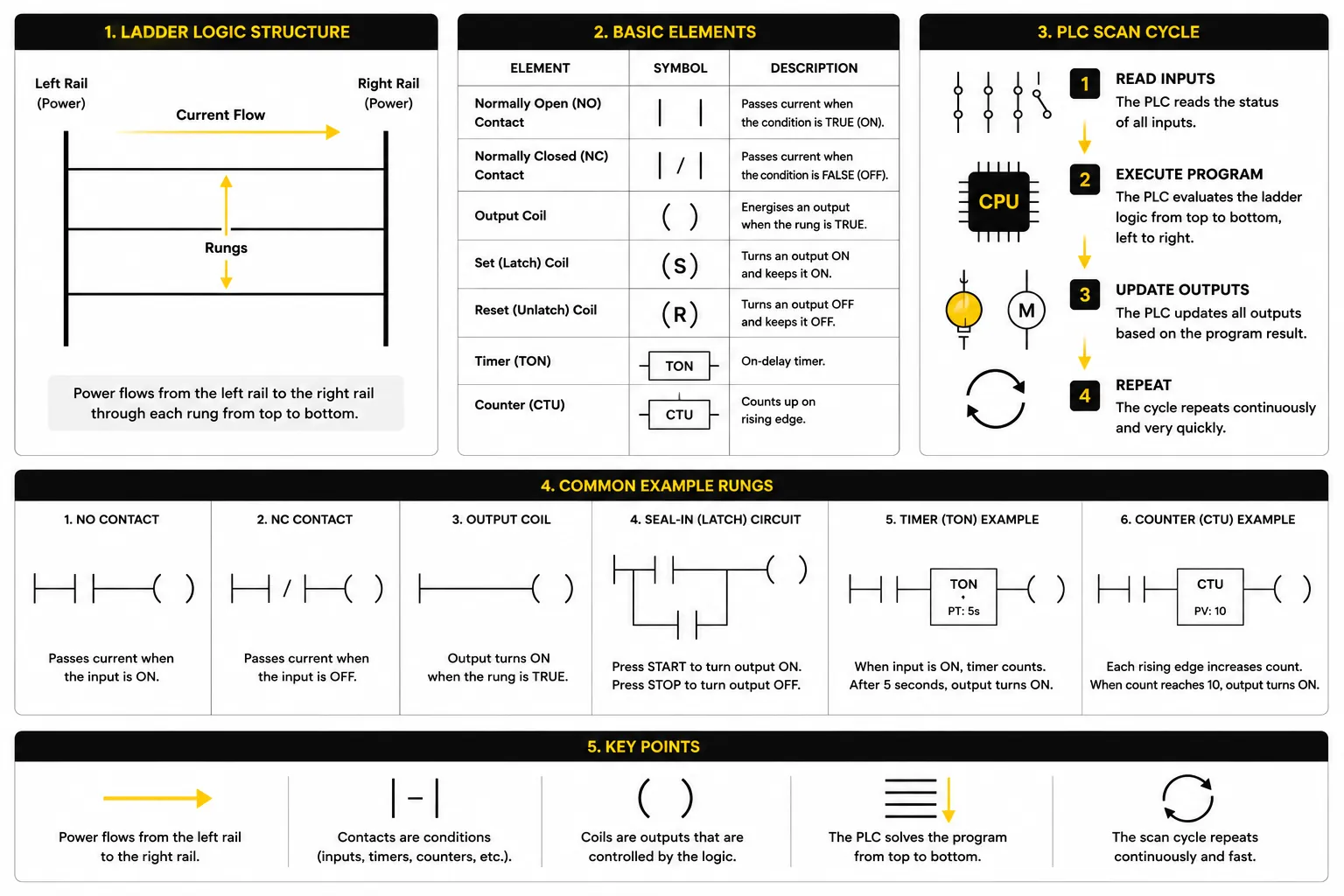
A Ladder Logic program is normally drawn between two vertical rails. The horizontal lines between those rails are called rungs. Each rung represents one piece of control logic, such as switching on a motor, turning on an indicator lamp or starting a timer.

The layout comes from older relay control drawings. Electricians and maintenance engineers were already used to reading circuits this way, so Ladder Logic made PLC programming feel more familiar when industry started moving from hardwired relay panels to programmable controllers.

Basic Ladder Logic diagram showing rails, rungs, contacts, coils and the PLC scan cycle
A simple Ladder Logic diagram showing the basic structure of a PLC program. Logic is evaluated from left to right, top to bottom during each PLC scan cycle.
LEFT RAIL                                      RIGHT RAIL
   |                                                   |
   |----[ Start PB ]----[/ Stop PB ]----( Motor )------|
   |                                                   |

Put simply, that rung says: if the start condition is true and the stop condition is healthy, energise the motor output.

Where it came from

Ladder Logic helped replace large hardwired relay systems.

Before PLCs became common, many machines were controlled with relays, timers and contactors wired together inside control panels. These systems worked, but they could be bulky, difficult to change and time-consuming to fault find.

If a machine sequence changed, the panel often needed physical rewiring. Ladder Logic helped solve that problem. Engineers could create similar control behaviour inside a PLC program, then change the logic in software rather than rebuilding the whole relay circuit.

Why it mattered

Same control thinking. More flexibility.

Ladder Logic kept the familiar look of relay control while giving engineers the flexibility of programmable automation. That is a big reason it became so widely adopted across industry.

How it works

Ladder Logic works as part of the PLC scan cycle.

A PLC does not usually read one rung and then stop. It repeats a fast cycle. It reads the input states, processes the ladder program from rung to rung, then updates the outputs. This repeats continuously while the controller is running.

01
Read the inputs

The PLC checks devices such as pushbuttons, sensors, selector switches, safety circuits and level switches.

02
Solve the rungs

The PLC evaluates each ladder rung using the current input states and internal memory bits.

03
Update the outputs

The PLC switches outputs such as lamps, contactors, valves, alarms and motor starters on or off.

This is why Ladder Logic feels so practical. You can often watch the rung states live in programming software and see how the real machine is responding.

Core building blocks

Most Ladder Logic starts with contacts, coils and simple instructions.

Different PLC brands use slightly different software and symbols, but the basic ideas are similar. Once you understand the core instructions, Ladder Logic becomes much easier to read.

NO

Normally open contact

A normally open contact is true when its related input or internal bit is on. It is often used for start buttons, sensor made signals and permissive conditions.

NC

Normally closed contact

A normally closed contact is true when its related input or internal bit is off. It is often used for stop buttons, fault conditions and healthy interlocks.

OUT

Output coil

An output coil turns something on in the PLC program. It may control a real output, such as a lamp or contactor, or an internal memory bit used elsewhere in the logic.

SET

Set and reset

Set and reset instructions can latch a signal on or off. They are useful, but they need careful design so the machine state remains clear and predictable.

TON

Timers

Timers allow logic to wait for a period before switching something. For example, a fan might run for ten seconds after a motor stops.

CTU

Counters

Counters count events such as parts passing a sensor, boxes reaching a station or cycles completed by a machine.

Simple example

A start/stop circuit shows Ladder Logic clearly.

One of the most common beginner examples is a motor start/stop circuit. The idea is simple: press the start button and the motor output turns on. Press the stop button and the motor output turns off.

In a real system, there would usually be more conditions. The PLC might also check an emergency stop circuit, a safety relay, an overload, a guard switch or a machine-ready signal. But the basic principle remains the same: the rung only allows the output when the required conditions are true.

   |----[ Start PB ]----[/ Stop PB ]----[/ Fault ]----( Motor Contactor )----|
   |                                                                          |
   |----[ Motor Contactor ]---------------------------------------------------|

The extra contact linked to the motor output is often called a seal-in or latch contact. It keeps the motor running after the start button is released, until a stop or fault condition breaks the rung.
Why it still matters

Ladder Logic is still used because it is visual, practical and easy to fault find.

Modern PLCs can often use several programming languages. Structured Text, Function Block Diagram and Sequential Function Chart all have their place. But Ladder Logic remains popular because it is easy to follow when you are standing in front of a machine trying to understand what is happening.

01

It is easy to read live

Engineers can monitor rungs online and quickly see which input, interlock or condition is preventing an output from turning on.

02

It suits discrete control

Machines with buttons, sensors, contactors, cylinders, valves and lamps often map naturally into Ladder Logic.

03

It feels familiar

For electricians and maintenance engineers, Ladder Logic often feels closer to electrical control drawings than text-based code.

PLC programming languages

Ladder Logic is one tool in the PLC programming toolbox.

No single PLC language is perfect for every task. Good automation engineers choose the right tool for the job, the site standards and the people who will maintain the system after commissioning.

LanguageOften useful for
Ladder LogicDiscrete machine control, start/stop circuits, interlocks, simple sequencing and maintenance fault finding.
Function Block DiagramProcess-style control, reusable blocks, analogue handling and visual signal flow.
Structured TextCalculations, data handling, loops, recipes and more complex algorithms.
Sequential Function ChartStep-by-step machine sequences where a process moves through defined stages.
Where you find it

Ladder Logic is common across practical industrial automation.

You will find Ladder Logic in many sectors because it is well suited to machines with clear input and output behaviour. It is especially useful where maintenance teams need to fault find quickly and understand the control sequence without digging through complex code.

ConveyorsPackaging machinesFood productionWater treatmentMachine toolsProcess skidsWarehouse systemsBuilding services
Common misconceptions

Ladder Logic is simple to start, but powerful when used properly.

“Ladder Logic is old-fashioned.”

Ladder Logic has been around for a long time, but it is still widely used on modern PLC platforms because it remains practical, visual and easy to support on site.

“Ladder Logic is only for electricians.”

Electricians often find it familiar, but controls engineers, maintenance engineers, technicians and apprentices all use Ladder Logic in industrial environments.

“Ladder Logic is just relay drawings.”

It is based on relay logic, but modern Ladder Logic can include timers, counters, comparisons, maths, data movement, function blocks and communication instructions.

Frequently asked questions

Ladder Logic FAQs

What is Ladder Logic?

Ladder Logic is a graphical PLC programming language that represents control logic using contacts, coils and horizontal rungs that resemble electrical relay circuits.

Why is it called Ladder Logic?

It is called Ladder Logic because the program is drawn with two vertical power rails and horizontal rungs, making it look like a ladder.

Is Ladder Logic still used?

Yes. Ladder Logic is still widely used in industrial automation because it is visual, practical and familiar to electricians, maintenance engineers and controls engineers.

Is Ladder Logic difficult to learn?

The basics are usually approachable for beginners, especially if they understand switches, relays and simple electrical control circuits. More advanced systems take practice and industrial experience.

Do Siemens PLCs use Ladder Logic?

Yes. Siemens PLCs can be programmed using Ladder Logic in TIA Portal, alongside other PLC programming languages such as Function Block Diagram and Structured Text.

Is Ladder Logic better than Structured Text?

Neither language is automatically better. Ladder Logic is often ideal for discrete machine control and fault finding, while Structured Text can be better for complex maths, data handling and algorithms.

Can you mix PLC programming languages?

In many PLC platforms, yes. A project may use Ladder Logic for machine interlocks, Function Block Diagram for analogue control and Structured Text for calculations or data handling.

Automation Fundamentals

Build automation capability with physical PLC concepts.

Explore the Rising Edge resource hub for practical explainers, industry insight and clear guidance built around real industrial systems.