
What are PLC inputs and outputs?
A PLC does not work on its own. It needs information from the machine or process, and it needs a way to control devices in response.
Inputs are signals going into the PLC. They tell the PLC what is happening. Outputs are signals going out of the PLC. They allow the PLC to control something.
Think of the PLC as the decision maker. Inputs give it information. The program makes a decision. Outputs make something happen.
Input. Logic. Output.
Most beginner PLC tasks can be understood with one simple flow: the PLC reads an input, runs the logic, then updates the output.
Input signal
A button, switch, sensor or device sends a signal into the PLC.
PLC logic
The PLC checks what should happen based on the input conditions.
Output signal
The PLC switches an output on or off, or sends a value to control a real device.
How PLC inputs work
PLC inputs are the signals the PLC receives from the outside world. They might come from an operator pressing a button, a sensor detecting an object, or a switch changing position.
In a typical 24V DC control system, an input is often seen by the PLC as either ON or OFF. The input does not usually power the machine directly. It gives the PLC information, and the PLC program decides what to do next.
How PLC outputs work
PLC outputs are the signals the PLC sends to control external devices. When the PLC program decides something should happen, it changes the state of an output.
A simple output might switch on a lamp. A more practical industrial output might energise a relay, start a contactor, activate a solenoid valve or signal another control device.
Digital vs analogue I/O
Digital I/O is simple ON or OFF behaviour. A button is pressed or not pressed. A lamp is on or off. A sensor is made or not made.
Analogue I/O uses a changing value. Instead of just ON or OFF, the PLC reads or sends a range, such as a speed, pressure, temperature, level or position value.
Simple example: start button and lamp
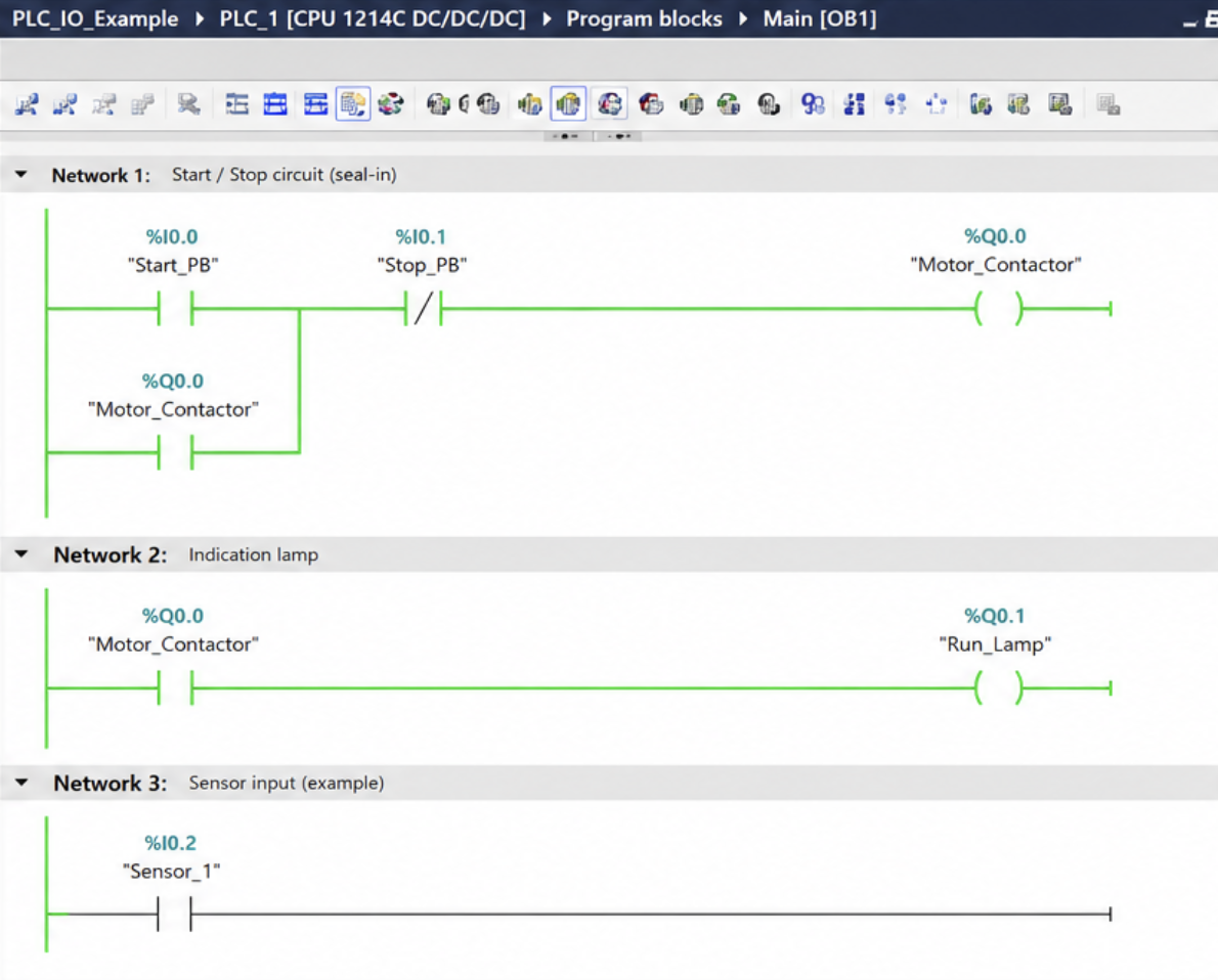
A simple start/stop circuit is one of the best ways to understand PLC inputs and outputs. The start button is an input, the stop button is another input, and the output could be a lamp, relay or contactor.
Press the button
The pushbutton sends an input signal to the PLC.
The PLC reads it
The PLC scan checks the input and runs the program logic.
The output switches
If the logic is true, the PLC turns the output on.
Common beginner mistakes
Beginners often think inputs control outputs directly. In reality, inputs give the PLC information and the program decides what outputs do.
Also watch out for scan cycle confusion, mixing up normally open and normally closed contacts, and ignoring the real wiring behind the software.