
What is the PLC scan cycle?
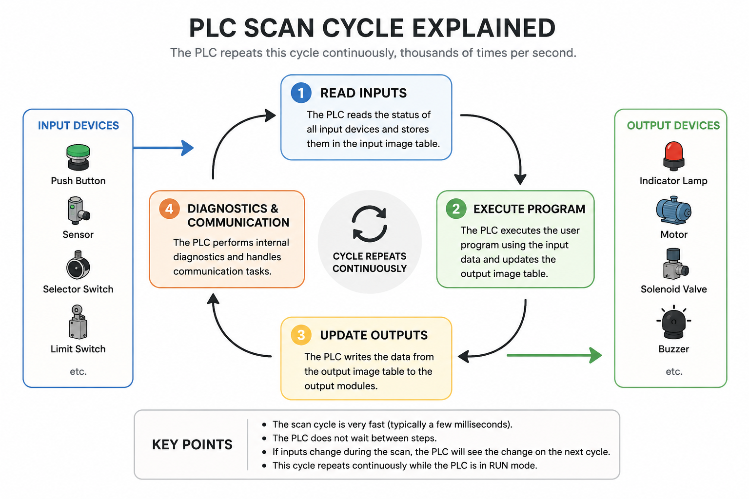
The PLC scan cycle is the repeating loop a PLC follows while it is running. Instead of doing one thing and stopping, the PLC keeps checking the system, running the program and updating the outputs.
That is what makes PLC control feel live. The PLC is constantly checking what is happening and deciding what should happen next.
Read inputs
The PLC checks buttons, switches, sensors and other input signals.
Run logic
The PLC follows the program written by the engineer.
Update outputs
The PLC switches lamps, relays, contactors, valves or other outputs.
Why does the scan cycle matter?
The scan cycle matters because a PLC does not simply react to one signal in isolation. It checks the full program repeatedly, which means timing, logic order and input conditions all matter.
When you understand the scan cycle, ladder logic starts to make more sense. You can see why an input may need to be true before an output turns on, why latching logic works, and why a fault might appear to happen “too quickly” to spot.
Step 1: The PLC reads the inputs
At the start of the scan, the PLC checks the input devices connected to it. These could be pushbuttons, selector switches, sensors, safety circuits or signals from another control device.
For a beginner, the key idea is simple: inputs tell the PLC what is happening in the real world.
Step 2: The PLC runs the program
Once the PLC knows the input states, it runs the control logic. In ladder logic, this usually means checking each rung and deciding whether each output instruction should be true or false.
This is where the program makes decisions. For example, the PLC might check if a start button is pressed, a stop button is healthy, and a safety circuit is made before switching an output on.
Step 3: The PLC updates the outputs
After the program has been scanned, the PLC updates the outputs. Outputs are the signals that control real devices such as lamps, relays, contactors, solenoid valves or alarms.
This is where the decision becomes action. The PLC has read the inputs, checked the logic, and now changes the physical outputs.
What is scan time?
Scan time is the amount of time it takes the PLC to complete one full scan cycle. In simple beginner projects, this is usually very fast.
As programs get larger, the scan time can increase. In most learning tasks, you do not need to obsess over it, but you should understand the principle. The PLC is not magic. It is repeatedly reading, processing and updating.
Simple example: push button and lamp
Imagine a green push button connected to a PLC input and a lamp connected to a PLC output.
You press the button
The input changes state and the PLC sees it on the next scan.
The program checks it
The ladder logic checks whether the input condition is true.
The lamp turns on
If the logic is true, the PLC updates the output and the lamp switches on.
Then the PLC does it all again. If you release the button and the logic is no longer true, the output may turn off on the next scan, depending on how the program is written.
Common beginner mistakes
A common mistake is thinking the PLC instantly connects an input directly to an output. That is not quite right. The input is read, the program is scanned, and then the output is updated.
Another common mistake is forgetting that the PLC repeats the program continuously. This is why latching circuits, timers, counters and edge detection can behave differently from what beginners first expect.
Why hands-on practice helps
The scan cycle becomes much easier to understand when you can press a real button, watch a real lamp, and see the ladder logic change online.
That is the whole point of hands-on PLC learning. You do not just read about inputs, outputs and logic. You build it, test it, break it, fix it, and make it click.