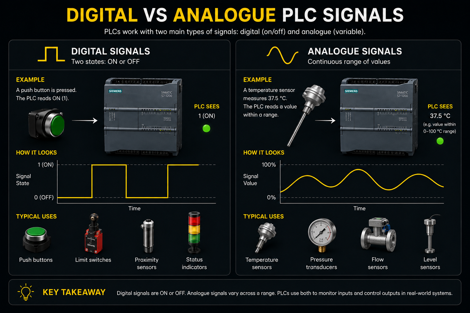
What is a digital PLC signal?
A digital PLC signal has two states: ON or OFF. In a typical 24V DC control system, the PLC sees the signal as either present or not present.
Digital signals are used for devices that only need a yes/no answer. Is the button pressed? Is the guard switch closed? Is the sensor detecting a part?
What is an analogue PLC signal?
An analogue PLC signal changes across a range. Instead of just ON or OFF, the value can move up and down.
Analogue signals are used when the PLC needs to measure or control something variable, such as level, speed, temperature, pressure or position.
Digital and analogue input examples
Inputs tell the PLC what is happening in the machine or process.
A digital input might come from a pushbutton, safety device or proximity sensor. An analogue input might come from a pressure transmitter, temperature sensor or potentiometer.
Digital input
A sensor changes from OFF to ON when it detects a product.
Analogue input
A level sensor sends a changing value as a tank fills or empties.
Digital and analogue output examples
Outputs are how the PLC controls external devices.
A digital output usually switches something on or off, such as an indicator lamp, relay or solenoid valve. An analogue output sends a changing control value, often to equipment such as a variable speed drive or control valve.
Why does this matter for beginners?
Understanding signal type helps you choose the right PLC module, wire devices correctly and write the correct logic. A pushbutton and a pressure transmitter do not behave the same way, so the PLC must treat them differently.
For beginner PLC learning, digital I/O is usually the best place to start. Once ON/OFF logic makes sense, analogue values become much easier to understand.
What should you learn next?
After digital and analogue signals, the next useful topic is internal PLC memory. Memory bits help you store logic states, latch conditions and organise a program more clearly.
How to choose whether a signal is digital or analogue
Ask one simple question: does the PLC only need to know yes or no, or does it need to know how much? If it is yes or no, it is usually digital. If it is a changing measurement, it is usually analogue.
A guard switch, push button, proximity sensor or pressure switch is often digital. It tells the PLC whether a condition exists. A pressure transmitter, temperature sensor or level transmitter is often analogue. It tells the PLC a measured value that changes over time.
Beginners should also understand scaling. The PLC may receive a raw number from an analogue module, but engineers normally convert that into useful units such as bar, degrees Celsius, percentage level or metres per minute.
Common beginner mistakes
- Thinking all PLC signals are just on or off. Digital signals are on/off, but analogue signals carry changing values.
- Forgetting to scale analogue values. A PLC may see a raw number that needs converting into pressure, level, temperature or speed.
- Confusing voltage level with signal type. 24V DC is commonly used for digital signals, but analogue signals can also use voltage ranges.
- Assuming analogue signals are always more accurate. Accuracy depends on the sensor, wiring, module, scaling and calibration.
Frequently asked questions
What is a digital PLC signal?
A digital PLC signal is simply on or off, such as a push button, limit switch, proximity sensor or indicator lamp.
What is an analogue PLC signal?
An analogue PLC signal represents a changing value, such as temperature, pressure, speed, level or flow. Common industrial examples include 0-10V and 4-20mA.
Is 24V DC digital or analogue?
24V DC is commonly used for digital control signals, but voltage itself is not automatically digital. A digital input normally treats the signal as either on or off.
Why is 4-20mA used in industry?
4-20mA is common because it is robust over longer cable runs and allows many systems to detect a broken wire when the signal drops below the expected live range.
Can one PLC use both digital and analogue signals?
Yes. Many PLC systems use digital inputs and outputs for on/off devices and analogue channels for measured values such as pressure, temperature and level.
Are analogue signals harder to program?
They can be slightly harder because the PLC usually needs to scale the raw signal into a real engineering value, such as bar, degrees Celsius or millimetres.